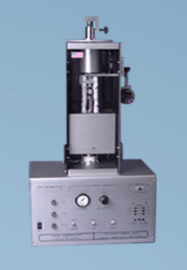
열전도도측정기 (열유속법)
UNITHERM™ 2022
특징
본 제품은 정상상태(steady state)에서 열평형에 도달한 시편의 열저항을 측정하는 열전도도측정기로써 고체 및 액체, 분말, 고분자 멜트, 박막에 이르기 까지 매우 다양한 시료의 열전도도를 매우 재현성 있게 측정하는 Guarded Heat Flow meter 입니다.
.
온도범위 / 측정범위
-20 °C / RT / 50 °C - 300 °C [Temperature range]
0.1 - 40 W/mK [Thermal conductivity range]
▣ Guarded Heat Flow Meter 법 (Steady state method)
▣ Fully computerized operation
▣ 시료직경: 1 or 2 inch dia. sample (square / round)
▣ ASTM E1530
▣ 열전도도 측정범위: 0.1 - 40 W/mK
▣ 박막, 액체, 파우더, 고분자 멜트의 열전도도측정
▣ 측정온도: -20 °C to 300 °C / RT to 300 °C/ 50 °C to 300 °C
Unitherm™ Model 2022는 고분자, 세라믹, 복합체, 유리, 고무, 일부 금속 등 다양한 재료의 열전도도(medium thermal conductivity)를 측정하는데 사용된다.
비교적 작은 시료의 측정에 유리하며, 페이스트류나 액체와 같은 비 고체상 재료는 전용 컨테이너를 사용해 측정할 수 있다. 박막 필름은 multi-layer 측정기법을 이용해 정확히 측정할 수 있다. 시험방법은 ASTM E1530 Standard 에 일치한다. |
|
 |
GUARDED HEAT FLOW METER TEST METHOD
A sample of the material is held under a uniform compressive load between two polished surfaces, each controlled at a different temperature. The lower surface is part of a calibrated heat flow transducer. The heat flows from the upper surface, through the sample, to the lower surface, establishing an axial temperature gradient in the stack. After reaching thermal equilibrium, the temperature difference across the sample is measured along with the output from the heat flow transducer. These values and the sample thickness are then used to calculate the thermal conductivity. The temperature drop through the sample is measured with temperature sensors in the highly conductive metal surface layers on either side of the sample.
• -20°C to 300°C
• Guarded Heat Flow Meter
• Fully computerized operation
• 1 or 2 inch dia. sample
• ASTM E1530
Each instrument is factory calibrated using samples of known thermal resistance, spanning the particular range. The contact resistance is kept small by applying a reproducible, pneumatic load to the test stack, and if needed, a thermally conductive interface compound. A guard furnace surrounds the test stack to reduce the effect of heat transfer across the edges of the sample. For testing at temperatures below ambient, the device is supplied with an airtight compartment, where the atmosphere can be kept relatively moisture free with dry air purge. Polymers can be tested through the melt using special containment cells. Also, special containment cells are available for fluids, pastes, and powders.
It typically takes from 45 to 60 minutes to complete a test at a temperature.
It is unavoidable to have a substantial temperature difference between the cold face of the sample and the heat sink. For this reason, a city water cooled heat sink allows operation with a lowest sample temperature of about 50°C. To fully utilize the range of the instrument, the optional chiller circulator is used, that can provide heat sink temperature to -10°C. The instrument is provided with one of three operating range modules. Each module covers a different thermal resistance region. The various modules are field exchangeable.
THE COMPUTERIZED SYSTEM includes Windows™ operating and data analysis software (PC not included). The user must specify certain test parameters, including sample size and desired test temperatures, and the equipment runs unattended until test completion, when thermal conductivity results are printed and plotted. Requires RS-232 serial port and USB port.
OPTIONAL FEATURES include an adjustable Constant Thickness Stop , which prevents the ram to squeeze the sample out if it happens to soften. This eliminates the need for the commonly employed spacers, which are difficult to use.
OPTIONAL CHILLERS
P/N 106831 for temperature range 0°C to 300°C
P/N 106832 for temperature range -20°C to 300°C
|