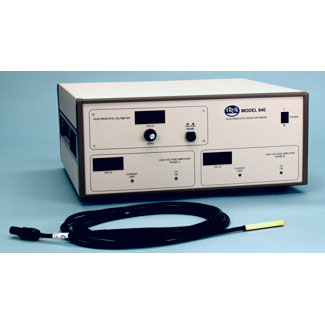
Electrstatic Chuck [ESC] Optimizer
Model 640
The Trek Model 640 Electrostatic Chuck Optimizer system allows Scientists and Engineers the freedom to experiment and optimize the waveforms and voltages required by an electrostatic chuck/clamp. The Model 640 system can be used to research, facilitate, and discover the exact waveform to minimize the de-clamp time and the precise voltage amplitude to maximize clamp force and maintain optimum wafer processing for your particular ESC operation.
This software driven test system combines two amplifiers [for two-phase voltage combinations] and a waveform generator, which can be independently programmed and configured to investigate, research, and discover the perfect power supply and waveform recipe to efficiently drive your ESC application.
This software accepts parameters through arbitrary data input, pre-programmed waveforms, or imported from your own Microsoft Excel CSV files. This method of generating waveform files expedites this process by making the ability to customize waveforms simple, yet powerful enough to generate the most complex waveforms that can be envisioned by the user. The Model 640 ESC Optimizer enables the user to build the waveform process in three stages.
The individually programmed stages include: the Clamp Signal Stage, the Processing Signal Stage (with options to “loop” the process cycle), and the Declamp Stage. All test data is recorded and presented in numerical and graphical format with a color coded display to visually cue successes or failures. The graphs can also be used to troubleshoot mechanical and electrical problems within your ESC operation.
An electrostatic voltmeter (ESVM) is contained in this system to optionally monitor any residual voltage from the clamping/de-clamping process.
These waveforms can then be used to specify operation parameters to build OEM amplifiers to meet the needs of your individual process. Once a finalized recipe is determined for optimizing your process, a permanent ESC power supply can be ordered for your system to ensure continuous, stable and consistent ESC processing.
Phase a & b Outputs
- Phase A Output Voltage Range
0 to ±2 kV DC or peak AC (4 kV p-p).
Phase A Output Current Range
0 to ±5 mA DC or peak AC (10 mA p-p).
Phase B Output Voltage Range
0 to ±2 kV DC or peak AC (4 kV p-p).
Phase B Output Current Range
0 to ±5 mA DC or peak AC (10 mA p-p).
PERFORMANCE (each phase)
Large Signal Bandwidth (1% distortion)
DC to greater than 1.2 kHz.
Small Signal Bandwidth (-3 dB)
DC to greater than 5 kHz.
Slew Rate (10% to 90%, typical)
Greater than 15 V/ms.
Settling Time (to 1%)
Less than 300 ms for 0 to 2 kV step.
DC Accuracy
Better than 0.1% of full scale.
Offset Voltage
Less than 500 mV.
Output Noise
Less than 100 mV rms (measured using the true rms feature of the Hewlett Packard Model 34401A digital multimeter).
Drift with Time
Less than 100 ppm/hour, noncumulative.
Drift with Temperature
Less than 350 ppm/°C.
|